Mechanical Animation: Show How Your Machine Works in 3D, from a Spec Sheet
The camera only sees the outside. Attach specs, cross-section drawings, or CAD files, and the AI uses the facts in your documents to make the casing see-through or cut it open to show the parts inside, then builds scenes in the order things move. No 3D software or video editing knowledge needed.
Who it's for
- For design and engineering people who want sales staff and distributors to be able to explain how a machine or equipment works
- For people who want to show operating steps in video that cross-section or assembly drawings can't convey
- For people who want video that shows internal motion on trade show monitors or product pages
- For people whose products can't be made into cutaway models or carried around
Common challenges
Drawings only communicate to people who can read them
Cross-section and assembly drawings may be enough for designers, but sales reps and customers can't tell which part moves when. Explanations end up relying on talking and pointing.
Cutaway models are hard to make and hard to carry
Cutaway models of real equipment take a lot of work to make, and their size is limited for bringing to sales meetings or trade shows. They stay still, so they can't show the order in which parts move.
You can't film the inside while it's running
Rotating parts of running machines are covered, so you can't open them and film while the machine runs. Even if you stop and disassemble the machine to film it, the order of operation doesn't show.
What 3DCG Video AI can do
See-through, opened up, and cutaway views
In the DR-5 power driver sample, "What's Inside" turns the shell see-through and lines up the parts inside. In the centrifugal pump sample, "Inside the Pump" cuts the casing open to show the impeller, and in the 4-stroke engine sample, "Inside the Engine" is a cross-section. You can tell the AI in chat, scene by scene, what you want to show and how.
Turn operating steps into scenes in order
The 4-stroke engine sample shows intake, compression, power, and exhaust one scene at a time, and the robot arm sample goes from computing the target angles to moving the hand along its path. If you attach a procedure document, the AI writes the storyboard in that order, so you can check for gaps and sequence before the build.
Even invisible flows and forces, shown with color and particles
The centrifugal pump sample shows water particles flying outward from the impeller ("Flinging Water Outward") and shows pressure changes with color and a pressure gauge ("Speed Becomes Pressure"). Both are illustrations for explanation, not analysis results.
You can also attach CAD files and drawings
Attach a 3D model such as STEP, and its shape can be used in your video. We recommend DXF for drawings. Part name labels and headings are drawn inside the 3D scenes, so the text is less likely to get distorted.
Examples of videos you can make
- The steps a press-fit machine takes to push a part in (lowering, positioning, pressing, return)
- Pressure changing inside a hydraulic cylinder and the rod moving
- How air is squeezed and compressed inside a screw compressor
- The order in which an automatic packaging machine opens a bag, fills it, and closes it
- How a cam and indexing mechanism turn a table by a fixed angle each step
- How a torque limiter slips to prevent overload
Sample videos similar to this use case
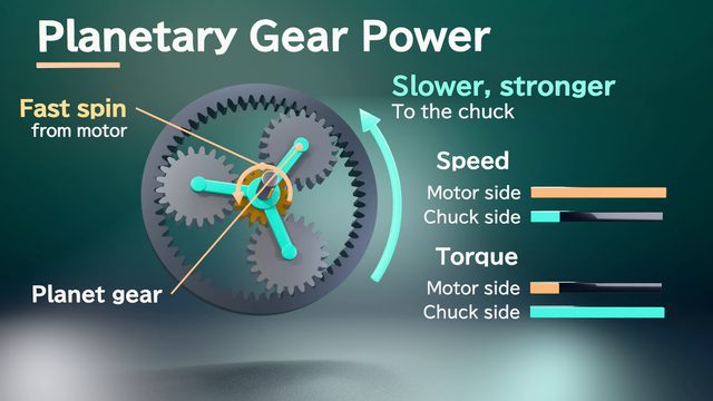
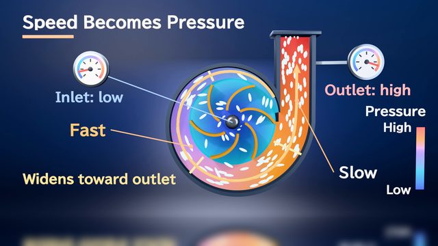
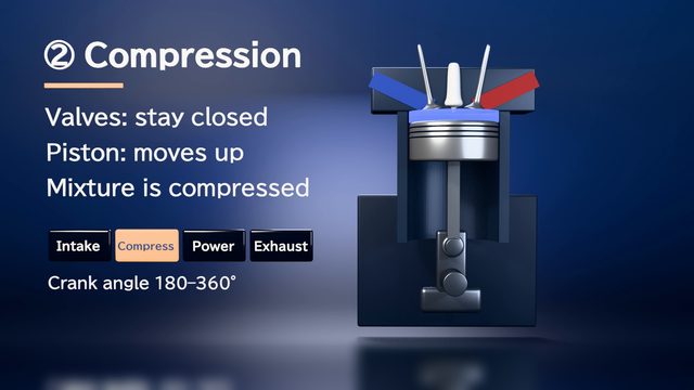
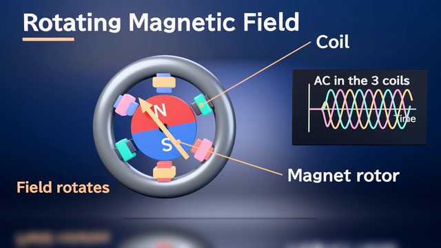
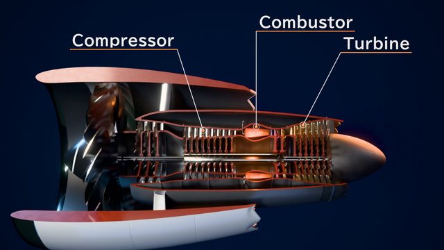
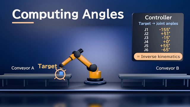
The DR-5 power driver is a fictional product, and the other samples explain machines in general. None of the samples used CAD data, and none were made from customer drawings or CAD files.
Tips for better results
Operating-step videos are easier to follow if each one focuses on a single action. In the samples, one minute holds about 7 scenes, with one point per scene. In your procedure document, write not only the order of the steps but also which part moves, what triggers it, and which direction it goes. A cross-section or assembly drawing gives cues for shape. If you ask scene by scene, such as "make the casing see-through here" or "cut it open here," that is reflected in the storyboard. Leave interior parts you don't want made public out of your documents, and tell the AI "simplify this part." Have your design engineer check the order of motion and the part names at the storyboard stage.
Example chat requests
Using the attached spec sheet and cross-section drawing, make a 90-second video explaining how the press-fit machine works and its operating steps. Make the exterior see-through to show the internal parts, and show the 4 steps (lowering, positioning, pressing, return) in order, one scene each. Label the part names. It will play on a trade show monitor, sometimes without sound, so please keep headings and captions short.
Price estimates
In Standard mode, one 1-minute video with 2 small revisions costs about 3,500 credits (1 credit = $0.01). High Quality mode costs about 7,100 to 12,000 credits. There's no monthly fee, and before each run we show you an estimate and a cap on the credits to be used.
Typical costs of 3D explainer videos (compared with production companies) · Pricing
FAQ
Which sample videos show cutaway and see-through effects?
The shell turns see-through in the DR-5 power driver ("What's Inside") and the electric car drive system ("Inside an Electric Car"). Cross-sections appear in the 4-stroke engine ("Inside the Engine") and the centrifugal pump ("Flinging Water Outward"). The cowling opens onto a cross-section in the jet engine (High Quality mode, "Inside the Engine"). How things are cut away or made see-through varies by product, so check the still images for yours.
Can you make videos that show disassembly or assembly steps?
We don't have a sample focused on disassembly or assembly yet, so we can't promise the result. How far CAD files split into parts can be animated is also still being tested. First, check whether a video of the internal structure and operating steps covers the explanation you need.
Will the motion and flow match the real machine?
These are motions made for explanation, not simulation or analysis results. We aim to use figures such as rotation speed and pressure from your documents, but errors are possible. Don't use the video as a document showing performance; have your design engineer check the order of motion and the numbers.
Can you build to the exact shape of real machine drawings or CAD data?
Attach a 3D model such as STEP, and its shape can be used in your video. Drawings (DXF) serve as cues for dimensions and shape, and the AI builds the 3D model from your documents, so fine details may be simplified. We are still working on verification with data exported from real CAD software.
Make a mechanical animation from your documents and a chat
Just attach your materials and tell the AI in chat what video you want. The AI plans a storyboard, builds 3D visuals, and makes a video with narration and captions.